Harman-kardon AVR4500 User Manual
Browse online or download User Manual for Receivers and Amplifiers Harman-kardon AVR4500. Harman-Kardon AVR4500 User Manual
- Page / 70
- Table of contents
- TROUBLESHOOTING
- BOOKMARKS
- OWNER’S MANUAL 1
- Table of Contents 2
- Declaration of Conformity 2
- Introduction 3
- Safety Information 4
- Front Panel Controls 5
- 230 V/50Hz 9
- AC OUTLETS 9
- ~230V/50Hz 9
- UNSWITCHED / 100W MAX 9
- SWITCHED / 50W MAX 9
- Rear Panel Connections 10
- Main Remote Control Functions 11
- DISC SKIP 14
- Installation and Connections 15
- System Configuration 20
- Operation 29
- Figure 9 34
- Advanced Features 37
- Multiroom Operation 39
- Tuner Operation 40
- Programming the Remote 42
- Function List 48
- Setup Code Table: TV 50
- Setup Code Table: VCR 56
- Setup Code Table: CABLE 61
- Setup Code Table: CD 62
- Setup Code Table: SAT 64
- Setup Code Table: DVD 67
- Troubleshooting Guide 68
- Technical Specifications 69
Summary of Contents
AVR 4500 Audio/ Video ReceiverOWNER’S MANUALPower for the Digital Revolution™®
10 REAR PANEL CONNECTIONSRear Panel ConnectionsCDVD Video Inputs: Connect these jacks tothe composite or S-Video output jacks on a DVDplayer or other
0123456789ABCDEFGHIJKLMNOPQMAIN REMOTE CONTROL FUNCTIONS 11Main Remote Control FunctionsPower On ButtonIR Transmitter WindowProgram/SP
12 MAIN REMOTE CONTROL FUNCTIONSMain Remote Control FunctionsIMPORTANT NOTE: The AVR4500’s remote maybe programmed to control up to seven devices,incl
MAIN REMOTE CONTROL FUNCTIONS 13KTuning Up/Down: When the tuner is in use,these buttons will tune up or down through theselected frequency band. If th
14 ZONE II REMOTE CONTROL FUNCTIONSZone II Remote Control Functions åPower Off∫AVR SelectorçAM/FM Tuner Select∂Input Selectors≠Tuning Up/Down – Fast P
INSTALLATION AND CONNECTIONS 15After unpacking the unit, and placing it on a solidsurface capable of supporting its weight, you willneed to make the c
16 INSTALLATION AND CONNECTIONSInstallation and ConnectionsSCART A/V ConnectionsFor the connections described above your videodevice needs RCA (cinch)
INSTALLATION AND CONNECTIONS 17Installation and ConnectionsBlackYellowRedFigure 1:SCART/Cinch-Adapter forplayback;signal flow:SCART → CinchBlackRedBl
18 INSTALLATION AND CONNECTIONSSystem and Power ConnectionsThe AVR 4500 is designed for flexible use withmultiroom systems, external control component
INSTALLATION AND CONNECTIONS 19Installation and ConnectionsSpeaker SelectionNo matter which type or brand of speakers isused, the same model or brand
2 TABLE OF CONTENTS3 Introduction4 Safety Information4 Unpacking5 Front Panel Controls7 Front Panel Information Display9 Rear Panel Connections11 Main
20 SYSTEM CONFIGURATIONSystem ConfigurationOnce the speakers have been placed in the roomand connected, the remaining steps are to pro-gram the system
SYSTEM CONFIGURATION 21the settings for each input individually, you willneed to make these adjustments for each inputused. However, once they are mad
22 SYSTEM CONFIGURATIONSystem Configuration2. When the SPEAKER SETUP menu firstappears, the on-screen cursor ›will be at the topof the list of speaker
SYSTEM CONFIGURATION 23and right bass frequencies under the crossoverfrequency selected in the next option settingon this menu, as described below.9.
24 SYSTEM CONFIGURATIONSystem ConfigurationAVR 4500 will not appear unless a digital sourceis selected and playing the correct bitstream.Note: When a
SYSTEM CONFIGURATION 25System Configuration2. Measure the distance from the listening/ view-ing position to the surround speakers.3. Subtract the dist
26 SYSTEM CONFIGURATIONSystem ConfigurationOutput Level AdjustmentOutput level adjustment is a key part of theconfiguration of any surround-sound prod
SYSTEM CONFIGURATION 27System Configuration8. After the test noise has circulated oncethrough each channel, it will send the tone toeach channel once
28 SYSTEM CONFIGURATIONWhen all channels have an equal volume level,the adjustment is complete. Now turn theVolumedown to about -40dB, otherwisethe l
OPERATION 29OperationSurround Mode ChartMODE FEATURES DELAY TIME RANGEDOLBY DIGITAL Available only with digital input sources encoded with Dolby Digi
INTRODUCTION 3IntroductionThank you for choosing Harman Kardon! With the purchase of a Harman Kardon AVR 4500 you are about to begin many years oflist
30 OPERATIONOperationSurround Mode ChartMODE FEATURES DELAY TIME RANGEHALL 1 The two Hall modes create sound fields that resemble a small (HALL1) or D
OPERATION 31OperationBasic OperationOnce you have completed the setup and configu-ration of the AVR 4500, it is simple to operateand enjoy. The follo
32 OPERATIONOperation Surround Mode SelectionOne of the most important features of the AVR 4500 is its ability to reproduce a full multi-channel surro
OPERATION 33Operation DTSDTS is another digital audio system that is capa-ble of delivering 5.1, 6.1 or 7.1 audio. Althoughboth DTS and Dolby Digital
34 OPERATIONOperation To select a digital source such as DVD, first selectits input using the remote or front panel InputSelector4%as outlined in this
OPERATION 35Operation a DVD is put into a Pause mode. The flashingindicators remind you that the playback hasstopped due to the absence of a digital
36 OPERATIONOperation the Selector buttons 7$or the ⁄/¤buttons Dto raise or lower the level. DO NOTuse the volume control, as this will alter the ref-
ADVANCED FEATURES 37Advanced FeaturesThe AVR 4500 is equipped with a number ofadvanced features that add extra flexibility tothe unit’s operation. Whi
38 ADVANCED FEATURESAdvanced FeaturesSemi-OSD SettingsThe semi-OSD system places one line messagesat the lower third of the video display screenwhenev
MULTIROOM OPERATION 39Multiroom OperationThe AVR 4500 is fully equipped to operate as thecontrol center for a multiroom system withoptional external
4 SAFETY INFORMATIONSafety InformationImportant Safety InformationVerify Line Voltage Before UseYour AVR 4500 has been designed for use with220-240-Vo
40 TUNER OPERATIONTuner OperationBasic Tuner OperationThe AVR 4500’s tuner is capable of tuning AM,FM and FM Stereo broadcast stations and receiv-ing
OPERATION 41Tuner OperationRDS OperationThe AVR 4500 is equipped with RDS (Radio DataSystem), which brings a wide range ofinformation to FM radio. No
42 PROGRAMMING THE REMOTEThe AVR 4500 is equipped with a powerfulremote control that will control not only thereceiver’s functions, but also most popu
PROGRAMMING THE REMOTE 43Programming the RemoteCode Readout When the code has been entered using the AutoSearch method, it is always a good idea to f
44 PROGRAMMING THE REMOTEProgramming the Remote5. The Program/SPL Indicator2will turn off,the red light under the Input Selector will flashon and off
PROGRAMMING THE REMOTE 45Programming the RemoteProgrammed Device FunctionsOnce the AVR 4500’s remote has been pro-grammed for the codes of other devi
46 PROGRAMMING THE REMOTEProgramming the RemoteChannel Control Punch-ThroughThe AVR 4500’s remote may be programmed tooperate so that the channel cont
PROGRAMMING THE REMOTE 47Programming the RemoteResetting the Remote MemoryAs you add components to your home-theater sys-tem, occasionally you may wi
48 FUNCTION LISTFunction List No. Button Name AVR Function DVD CD/CDR1 Power On Power On Power On Power On2 Power Off Power Off Power Off Power Off3 M
FUNCTION LIST 49Function List No. Button Name Tape VCR (VID 1) TV (VID 2) CBL (VID 3) SAT(VID 3)1 Power On Power On Power On Power On Power On Power
FRONT PANEL CONTROLS 51Main Power Switch: Press this button toapply power to the AVR 4500. When the switchis pressed in, the unit is placed in a Stand
50 SETUP CODESSetup Code Table: TV Maker (Brand) Name Code Number (3digit) ListACURA 195ADMIRAL 065 171 262 279 324AKAI 019 049 050 063 102 123 133 13
SETUP CODES 51Setup Code Table: TV (continued)Maker (Brand) Name Code Number (3digit) ListDECCA(UK) 046 050 102 106 131DEGRAAF 023 122 209 262DIXI 06
52 SETUP CODESSetup Code Table: TV (continued)Maker (Brand) Name Code Number (3digit) ListHIGASHI 050HINARI 004 018 042 049 066 119 123 133 139 143 19
SETUP CODES 53Setup Code Table: TV (continued)Maker (Brand) Name Code Number (3digit) ListMITSUBISHI 013 018 019 021 049 063 065 105 124 131 132 143
54 SETUP CODESSetup Code Table: TV (continued)Maker (Brand) Name Code Number (3digit) ListPYE 050 063 065 079 112 157 158 160 188 250QUASAR 045 046 06
SETUP CODES 55Setup Code Table: TV (continued)Maker (Brand) Name Code Number (3digit) ListSONOKO 050 063 076 195SONY 012 018 028 131 143 204 208 211 2
56 SETUP CODESSetup Code Table: VCR Maker (Brand) Name Code Number (3 digit) ListAGASHI 155AIOSTAY 148AIWA 039 044 055 073 112 116 121 148 152AKAI 028
SETUP CODES 57Setup Code Table: VCR (continued)Maker (Brand) Name Code Number (3 digit) ListDUAL 044 090 128 148 155DUMONT 015 039 054 148 155DYNATEC
58 SETUP CODESSetup Code Table: VCR (continued)Maker (Brand) Name Code Number (3 digit) ListKAMBROOK 148KANSAI 148KAPSCH 160KARCHER 042 054 134 155KEN
SETUP CODES 59Setup Code Table: VCR (continued)Maker (Brand) Name Code Number (3 digit) ListOCEANIC(ITT) 160OCEANUIC 149OLYMPUS 107 147OMAGA 148OPTONI
6 FRONT PANEL CONTROLSFront Panel Controls7Logic 7 Mode Selector /‹Button: Thisbutton has two functions: In normal use, press itto select one of the L
60 SETUP CODESSetup Code Table: VCR (continued)Maker (Brand) Name Code Number (3 digit) ListSINGER 155SINUDYNE 054 078 146 155 160SOLAVOX 149 160 162S
SETUP CODES 61Setup Code Table: VCR (continued)Maker (Brand) Name Code Number (3 digit) ListWATSON 155 159WATTRADIO 159 160WELTBLICK 155WHITE WESTINGH
62 SETUP CODESSetup Code Table: CD Maker (Brand) Name Code Number (3 Digit) ListADC 012ADCOM 049 063 069AIWA 072 111 118 156 170AKAI 050 177 184ARCAM
SETUP CODES 63Setup Code Table: CD (continued)Maker (Brand) Name Code Number (3 Digit) ListNSM 051ONKYO 037 038 045 046 171 175 202 203OPTIMUS 020 03
64 SETUP CODESSetup Code Table: SATMaker (Brand) Name Code Number (3digit) ListAIWA 441AKAI 333ALBA 301 317 324 356 370 411 415 417 426ALDES 433ALLSON
SETUP CODES 65Setup Code Table: SAT (continued)Maker (Brand) Name Code Number (3digit) ListKOSMOS 380KRIESLER 353KYOTO GMI ATLAN 443LEMON 474LENCO 37
66 INTRODUCTIONSetup Code Table: SAT (continued)Maker (Brand) Name Code Number (3digit) ListSCHAUB LORENZ 388 399SCHNEIDER 353SENTRA 337SIEMENS 338 39
INTRODUCTION 67Setup Code Table: DVDMaker (Brand) Name Code Number (3 Digit) ListAPEX DIGITAL 061CALIFORNIA AUDIO 040DENON 002 019 022 034 051GE 003
68 TROUBLESHOOTING GUIDETroubleshooting GuideProcessor ResetIn the rare case where the unit’s operation or thedisplays seem abnormal, the cause may in
TECHNICAL SPECIFICATIONS 69Technical SpecificationsAudio SectionStereo Mode Continuous Average Power (FTC)65 Watts per channel, 20Hz–20kHz,@ < 0.0
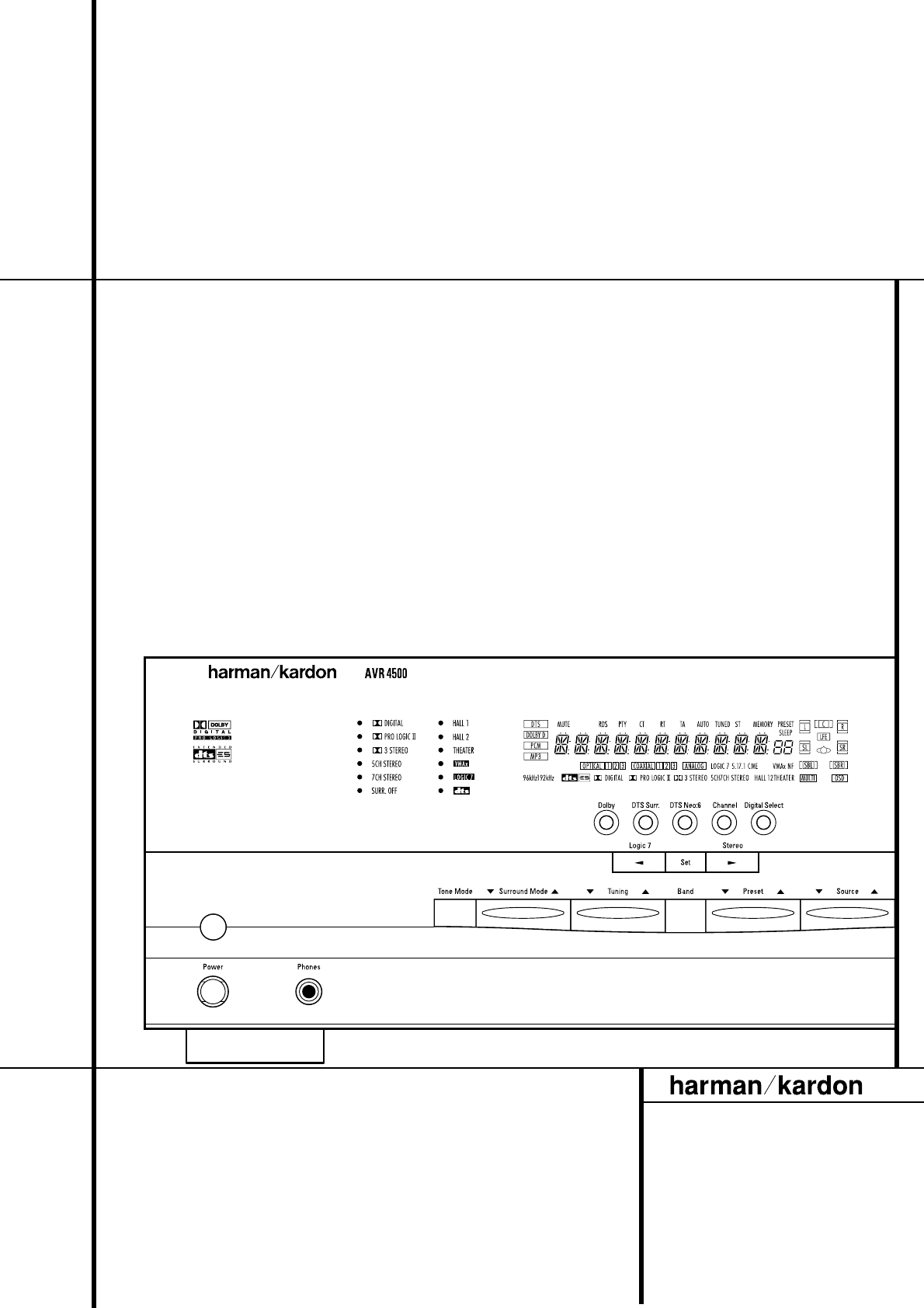
ABCDEFGHIJKLMNOPQRSTUVWXYZAA ABACADAEFRONT PANEL INFORMATION DISPLAY 7Front Panel Information DisplayBitstream IndicatorsOptical Source IndicatorsSam
250 Crossways Park Drive, Woodbury, New York 11797 www.harmankardon.comHarman Consumer International:2, route de Tours, 72500 Château-du-Loir, France©
8 FRONT PANEL INFORMATION DISPLAYFront Panel Information DisplayQSpeaker/Channel Input Indicators: Theseindicators are multipurpose, indicating either
REAR PANEL CONNECTIONS 9Rear Panel Connections489CEFHIJKLMNOPRSG5Q76BAD0b123aZYXWVUT230 V/50HzAC OUTLETS~230V/50HzUNSWITCHED / 100W MAXSWITCHED / 50W
Related products and manuals for Receivers and Amplifiers Harman-kardon AVR4500
 (64 pages)
 (14 pages)
© 2020, manymanuals.com. All rights reserved. | 1.481 s |
 Manymanuals.com
 Manymanuals.de
 Manymanuals.fr
 Manymanuals.it
 Manymanuals.pl
 Manymanuals.cz
 Manymanuals.es
 Manymanuals-pt.com
Comments to this Manuals